This maintenance guide provides comprehensive instructions on how to maintain an Antminer L7 properly. We will cover routine testing, locating faulty chips, re-soldering and replacing parts, making relevant maintenance/analysis records, assembling the machine for aging tests and more. This guide is designed to help you make sure your Antminer L7 is running at its optimal performance level with minimal downtime. Following the steps outlined in this guide will ensure that your miner remains in good condition for years.
Preparation and Maintenance Guidelines
It’s essential to take the time to properly prepare and maintain components before, during, and after installation. This includes applying thermal gel for better heat transfer, forming air ducts for better airflow, connecting power supplies in the correct sequence, fixing chips to prevent overheating, and ensuring test fixtures meet production requirements. Additionally, these guidelines should also include instructions on cleaning components with approved solvents such as isopropyl alcohol or distilled water, as well as how to store components away from extreme temperatures and humidity levels safely. Finally, regularly scheduled maintenance checks should be carried out every few months or at least annually to guarantee the proper functioning of all parts within the system.
Preparation Requirements for Repair Platform, Tools, and Equipment
I. Platform Requirements:
- To perform maintenance work, an anti-static maintenance workbench is required. It should be grounded, and an anti-static wristband and grounding are necessary.
II. Equipment Requirements:
- Constant temperature soldering iron (350°C-380°C) with a pointed tip for soldering small patches such as chip resistors and capacitors.
- Hot air guns and BGA rework stations are used for chip / BGA disassembly and welding.
- Multimeter with welded steel pins and heat-shrinkable sleeves for easy measurement. The recommended model is the Fluke 15b+ multimeter.
- Oscilloscope. The recommended model is UTD2102CEX+. A network cable is required for an internet connection and a stable network.
III. Test Tool Requirements:
ARC Kit
- ARC Antminer Hashboard Tester
- Lab PSU 10-30V / 1-15A
Bitmain Kit
- APW12 power supply: AP12_12V-15V_V1.2 and power adapter cable. It is recommended to use thick copper wire for the positive and negative poles of the power supply to connect the power supply and the power board and only limited to PT1 and maintenance test use.
- Use the test fixture of the V2.3 control board (test fixture material number ZJ0001000001). The positive and negative poles of the test jig need to be installed with discharge resistors. Using a cement resistance of 20 ohms and 100W or more is recommended.
IV. Maintenance Auxiliary Materials/Tools Requirements:
- Solder Paste 138°C, flux, Mechanic lead-free circuit board cleaner, and anhydrous alcohol.
- Mechanic lead-free circuit board cleaner cleans up the flux residue after maintenance.
- Thermally conductive gel is used to apply to the chip surface after repair.
- Ball-planting steel mesh, desoldering wick, and solder balls (the recommended ball diameter is 0.4mm).
- When replacing a new chip, it is necessary to tin the chip pins and then solder them to the hash board. Apply thermally conductive gel evenly on the chip’s surface, then lock the heatsink.
- Serial port code scanner.
- Serial port adapter board RS232 to TTL adapter board 3.3V.
- Self-made short-circuit probe (use the pins for wiring and welding and heat the shrinkable sleeve to prevent short-circuit between the probe and the small heatsink).
V. Common Maintenance Spare Material Requirements:
- 0402 resistor (0R, 10K, 4.7K,)
- 0402 capacitor (0.1uF, 1uF)
Maintenance Requirements
- When replacing a chip, pay attention to the operation method. After replacing any component, check that the PCB board has no obvious deformation. Check the replacement and surrounding parts for missing parts, open circuits, and short circuits.
- Maintenance personnel must have electronic knowledge, at least one year of maintenance experience, and proficiency in BGA/QFN/LGA packaging and welding technology.
- After repair, the hashboard must be tested more than twice, and all tests must pass.
- Check the tools to ensure that the test fixture can work typically. Determine the parameters of the maintenance station test software, the version of the test jig, and other related parameters.
- To test repairing and replacing the chip, test the chip first and then do the functional test after it passes. The functional test must ensure that the small heatsink is welded correctly, the large heat sink is installed, and the thermal adhesive gel is applied evenly. Two hash boards should be placed simultaneously to form an air duct when using the chassis to dissipate heat. For single-sided testing in production, the air duct must also be formed.
- When measuring the signal, use fans to dissipate heat and ensure the fans are at full speed.
- When powering on the hashboard, connect the negative copper cord of the power supply first, then the positive copper cord of the power supply, and finally, insert the signal cable.
- When disassembling, reverse the order of installation. First, remove the signal cable, then pull the positive copper cord of the power supply, and finally, remove the negative copper cord of the power supply. If you do not follow this order, it may cause damage to U1 and U2.
- Before testing the pattern, the repaired hashboard must cool down before testing; otherwise, it will lead to testing NG.
- Pre-tin the chip pins with solder paste to replace a new chip and then solder them to the PCB for repair.
Overview of Antminer L7 Components
L7 Hashboard Structure:
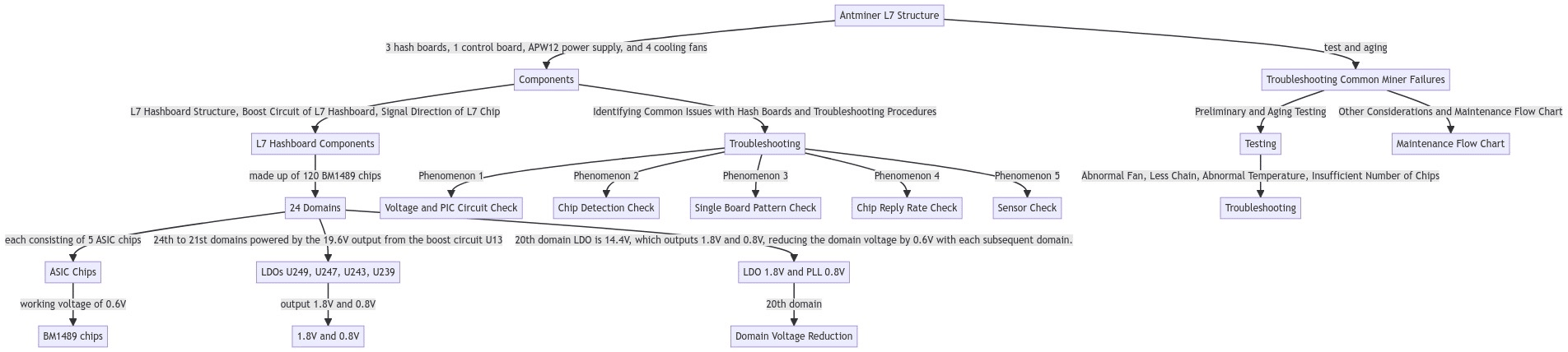
The L7 hash board is made up of 120 BM1489 chips, divided into 24 domains, each consisting of 5 ASIC chips. The BM1489 chips run on a working voltage of 0.6V. The 24th to 21st domains are powered by the 19.6V output from the boost circuit U13 to the LDOs (U249, U247, U243, U239), which output 1.8V and 0.8V. The power supply for the 20th domain LDO is 14.4V, which outputs 1.8V and 0.8V, reducing the domain voltage by 0.6V with each subsequent domain.
Boost Circuit of L7 Hashboard:
The L7 hash board’s boost circuit converts the 15V power supply to 19.6V, as shown in the diagram.
Signal Direction of L7 Chip:
- The CLK signal flows from Y1 and Y2 25M crystal oscillator, with Y1 providing signals for chips 1 to 60 and Y2 providing signals for chips 61 to 120. The voltage measured by the multimeter is around 0.8V-0.9V.
- The RST and CI signals flow from the IO port 3 pin (3.3V) into the level conversion IC U1-U3-U4 after conversion, and then transmitted from chip 01 to chip 120. The voltage is 0V when the IO line is not inserted, and 1.8V during operation.
- RX (RI, RO) signal flows from chip 120 to chip 01, through U1, back to pin 8 of the signal cable terminal, and then to the control board. The voltage is 0.3V when the IO signal is not inserted, and 1.8V during operation.
- BO (BI, BO) signal flows from chip 01 to chip 120, and the multimeter measures it as 0V.
Antminer L7 Structure:
The Antminer L7 consists of three hash boards, one control board, an APW12 power supply, and four cooling fans, as shown in the diagram.

Identifying Common Issues with Hash Boards and Troubleshooting Procedures
Phenomenon 1: The chip on the hash board is detected as 0 during single-board testing
- Check the output of the power supply and verify the voltage in the circled area of the picture.
- Check the voltage domain output. The voltage for each domain is around 0.6V, and the 15V power supply typically has the domain voltage. Start by measuring the power supply terminal output of the hash board and check whether the MOS is short-circuited (measure the resistor value between pins 1, 4, and 8). If there is no domain voltage despite 15V being powered, continue with the troubleshooting process.
- Check the PIC circuit. Verify if there is output on pin 11 of U6 with a voltage of around 3.2V. If there is output, continue with troubleshooting. If there is no 3.2V output, check the connection status of the test fixture cable and the hash board, and re-program the PIC.
- Check the boost circuit output. Verify if the voltage on C70 in the figure is 23V.
- Check the output of each group of LDO 1.8V or PLL 0.8V.
- Check the chip signal output (CLK/CI/RI/BO/RST). Measure the voltage value range as described by the reference signal direction. If there is a significant deviation in the voltage value during measurement, compare it with the adjacent group’s measurement value.
Phenomenon 2: The single-board detection cannot detect the chips
The Antminer Hashboard Tester you are using is indicating a lack of chips, the following steps can be taken to identify the problem:
- To troubleshoot this issue, first, measure the total voltage of the domain and the boost circuit. If the voltage averages 23V, use a short-circuit probe to short-circuit the RO and 1V8 test points between the 1st and 2nd chip. Then, run the testing program. If no chips are found at this point, there could be one of the following issues:
- Measure the voltages of the 1V8 and 0V8 test points using a multimeter. If the voltages are not 1.8V and 0.8V, it could be due to abnormal LDO circuits in this domain, or two ASIC chips in this domain may not be soldered well. Most often, this issue is caused by a short circuit of 0.8V and 1.8V chip filter capacitors. Measure the resistance value of chip filter capacitors related to the front and back of the PCBA.
- Check whether the circuits of U1 and U2 are abnormal, such as resistance soldering.
- Check whether the first chip has pins that are not soldered well. It is often found during maintenance that the pins are tin from the side, but they are removed. The chip is found that the pins were not tinned at all.
- If one chip is found in the previous step, the first chip and the previous circuit are all good. Use a similar method to check the following chips. For example, short-circuit the 1V8 and RO test points between the 38th and 39th chips. If the log can find 38 chips, the first 38 chips are okay. If 0 chips are still found, first check whether the 1V8 is normal. If it is normal, there is a problem with the chips after 38. Continue to troubleshoot until the problematic chip is found. Suppose there is a problem with the Nth chip. Then when the 1V8 and RO between the N-1th and Nth chips are short-circuited, the N-1 chip can be found. But not all chips can be found when 1V8 and RO between the Nth and N+1th chips are short-circuited.
- When a certain chip is consistently reported by the LCD display as ASIC NG, the value of the chip reported in each test usually does not change. In this case, the repair method can be carried out according to the maintenance method of measuring the signal voltage normally.
Phenomenon 3: Single Board Pattern NG, occurs when the reply nonce data is incomplete (for the PT2 station)
The problem of Single Board Pattern NG occurs due to a significant difference in characteristics between the affected chip and the other chips. The solution to this issue is to replace the affected chip with a new one. The replacement rule is determined by the screen prompt of the test fixture or the log information. In case the chip’s appearance is not damaged, the replacement should be the one with the lowest reply rate in each domain. If two chips are in the same domain, then the one with the lowest nonce should be replaced.
It’s important to keep in mind that the domain and asic numbers start from 0. Moreover, an abnormal voltage in the domain can also cause an insufficient response of the chip nonce.
Phenomenon 4: P:NG occurs when none of the chips are broken but the reply rate is not up to the standard
P: NG occurs when some of the chips have a poor reply rate. To fix this issue, you can check the log to determine the two chips with the lowest reply rate and replace them. This replacement will help to ensure that the overall reply rate reaches the standard.
It’s essential to note that an abnormal voltage in the domain can also lead to an insufficient response of the chip nonce.
Phenomenon 5: Sensor NG, Can’t read all sensor
To perform maintenance on Sensor NG, when testing PT1 & PT2, check the serial port print log to confirm if the temperature sensor reports an error. After that, check the temperature sensor circuit and measure whether the power supply of the 8th pin of the temperature sensor is 3.3V. Also, check whether the SDA and SCL buses are functioning properly.
For the PT2 test environment, the temperature should be maintained between 25℃ and 30℃. If the ambient temperature drops below 25℃, the software will stop the test.
In terms of PT2 test power supply requirements, the actual output voltage cannot be lower than 0.03V set in the configuration file when the PT2 test fixture power supply is under a load of 1500 watts (when testing a board). For instance, if the configuration file requires an output of 13.8V, the output voltage of the power supply cannot be lower than 13.77V when it is loaded with 1500 watts.
Troubleshooting Common Miner Failures
Preliminary test of the whole machine
Referring to the test process document, the general problems that arise are assembly process problems and control board process problems. Common problems include the inability to detect the IP, abnormal number of detected fans, and abnormal detected chain. If any issues arise during the test, they should be repaired according to the monitoring interface and the test LOG prompts. The maintenance methods for the initial test and the aging test of the whole machine are the same.
Aging Testing of the Miner
The aging test should be repaired according to the monitored interface test. For instance:
- Abnormal fan display: In such cases, we need to check whether the fan works normally, whether the connection with the control board is normal, and whether the control board is abnormal.
- Less chain: This means that three boards are missing one board. In most cases, there is a problem with the connection between the hash and control boards. Check the cable to see if there is an open circuit. If the connection is OK, you can test the board to PT2 to see if it can be tested. If it can be tested, it can basically be determined that it is the control board. If the test fails, use the repair method of PT2 maintenance.
- Abnormal temperature: Generally, the temperature is high. The maximum PCB temperature set by our monitoring system cannot exceed 90℃. The fan will alarm and it will not work normally. Generally, the ambient temperature is too high, and the abnormal operation of the fan will also cause abnormal temperature.
- Insufficient number of chips: If the number of chips is insufficient, you can refer to PT2 for testing and repair.
- After running for a period of time, there is no hashrate, and the connection of the mining pool is interrupted, check the network.
- The aging test state of the normal good miner:
If the miner still loses hashrate, reduce the frequency and other conditions remain unchanged. Let the miner mine to see if it will lose hashrate and whether the hash board will hit X. If it still hits X in losing hashrate, then remove the heat sink of the hashboard for mining and wait for the hashrate to drop. Measure whether the domain voltage is normal. Generally, the domain voltage will be abnormal in the problematic domain. Then measure the RI signal to see if the RI signal is broken. If the RI signal is missing, basically, the chip is short-circuited or damaged after being tinned.
Other Considerations and Maintenance Flow Chart
- Routine testing involves visually inspecting the hash board to check for any deformities or burn marks. After that, check for short circuits or open circuits and ensure that the voltage of each domain is around 0.6V.
- Once routine inspection is complete, use a test fixture to inspect the chip and determine its position.
- Check the chip test points, including CI/NRST/RO/XIN/BI and the voltages of VDD 0V8 and VDD 1V8, starting from the vicinity of the faulty chip.
- Trace the signal flow and locate any unusual points of failure. The CLK, CI, BI, and RST signals are transmitted in the forward direction (chips 1 to 120) except for the reverse transmission of the RX signal (chips 120 to 1).
- If a faulty chip is found, it must be re-soldered. Add flux around the chip, heat the solder joints of the chip pins until they dissolve, and re-grind and collect tin to re-tin the chip pins and pads. If the fault persists, replace the chip.
- Test the hash board at least twice to ensure it is functioning properly. Wait for the hash board to cool down before the second test.
- Keep records of maintenance and analysis for production, after-sales, and research and development purposes.
- After documentation, assemble the hash board into a complete machine for routine aging.
- Streamline good products from the first station of production.