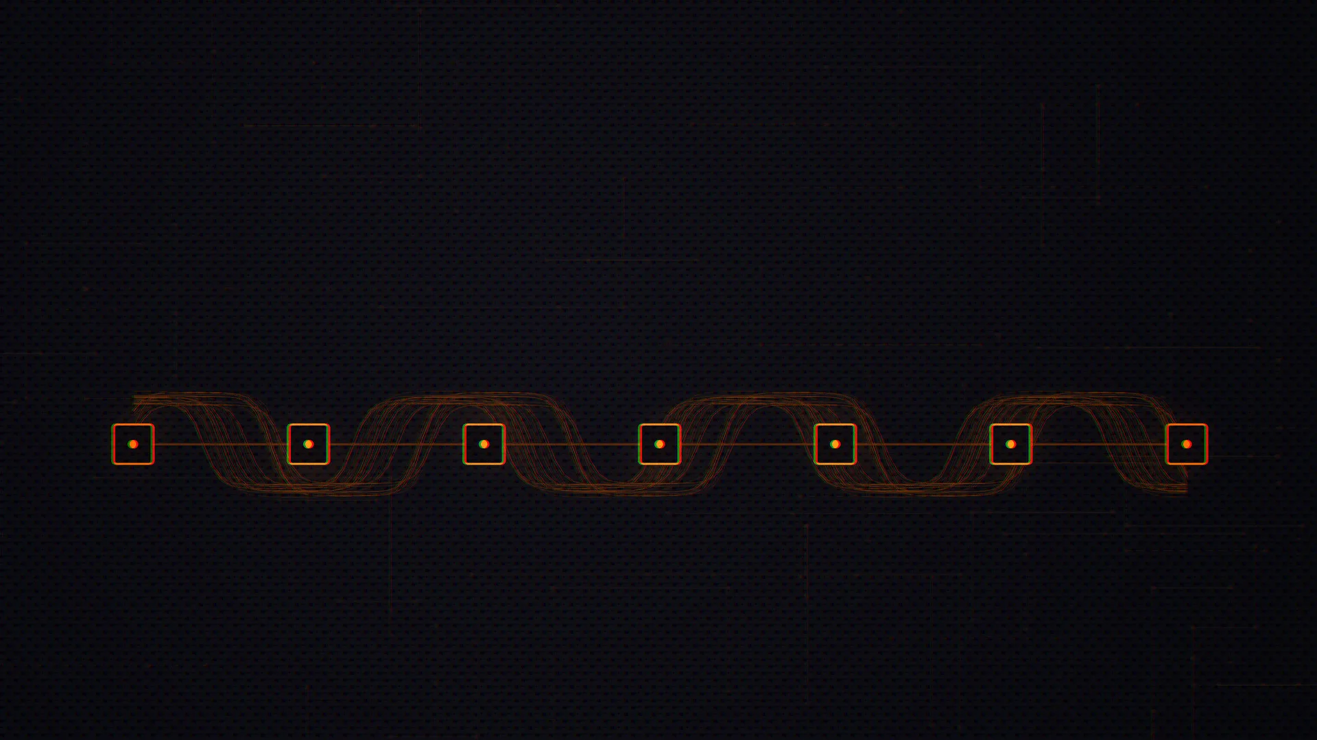
On a BM13xx hashboard, the ASIC chips form a daisy chain: clock, command and reset signals pass chip-to-chip, while responses flow back in reverse. One broken chip silently severs everything downstream, so the controller reports “chain X only N chips.” This guide shows how to scope the clock and reset chain and bisect to the first failing chip.
If you have ever pulled a hashboard, seen the dashboard report “Chain 1: 29 ASIC” instead of 108, and assumed you had 79 dead chips, this guide is for you. Almost always you have one bad chip — or one cold solder joint — and 79 healthy chips sitting silent behind it. Understanding the serial chain turns a confusing partial-detection symptom into a single, fixable coordinate on the board.
The chip-to-chip signalling described here was mapped out over years by the broader mining-repair community and by the open-source ESP-Miner / Bitaxe project, whose readable C drivers turned Bitmain’s undocumented BM-series protocol into something anyone can study. We stand on their shoulders. This is a generic, hardware-level reference — no firmware exploits, just the physics of the chain.
Why “chain X shows only N chips” is a serial-chain problem
A complete Antminer is a control board plus three hashboards. Each hashboard is a long string of identical ASICs — 76 on an S19 (BM1398), 108 on an S21 (BM1368), 91 on an S21 XP (BM1370), 110 on an S19 XP (BM1366) — wired in a daisy chain. The control board does not address each chip individually over a star bus. It pushes signals into chip 1, and chip 1 regenerates and forwards them to chip 2, which forwards to chip 3, and so on to the last chip on the board.
That topology is efficient and cheap to route, but it has one brutal property: it is only as strong as its weakest link. If chip 37 cannot forward the chain, chips 38 through the end of the string vanish from the controller’s view, even though they are powered and undamaged. The number the firmware reports — “29 ASIC“, “ASIC NG: 79” — is not a count of dead chips. It is the position of the first break. The reported count tells you roughly where to start looking, not how much is broken. This is the same root cause behind the classic “chain X only” symptom and many “dead ASIC” error reports.
The five signals that run the daisy chain
Five logical signals tie the control board to the ASIC string. Four flow forward (chip 1 toward the last chip); one flows backward (last chip toward chip 1). Get this direction map in your head before you touch a probe, because it dictates where a fault hides.
| Signal | Name | Direction | Role |
|---|---|---|---|
| CLK | Clock | Forward (1 → N) | 25 MHz master clock; the heartbeat every chip times itself against |
| CI / CO | Command In / Out | Forward (1 → N) | UART TX — commands and jobs from the controller |
| RI / RO | Response In / Out | Reverse (N → 1) | UART RX — nonces and register data returning to the controller |
| RST / nRST | Reset | Forward (1 → N) | Holds or releases the chain; asserted during init and error recovery |
| BI / BO | Busy In / Out | Forward (1 → N) | Work/flow-control handshake between chips |
Each chip has an input pin and a matching output pin for the forward signals: CLKI/CLKO for clock, CI/CO for commands, NRSTI/NRSTO for reset, BI/BO for busy. The chip’s output feeds the next chip’s input. The reverse channel is the mirror image: each chip’s RO drives the previous chip’s RI, so a found nonce ripples back up the string to the controller. The first hard fact to internalize: commands and clock travel one way, answers travel the other. A board can clock and accept commands perfectly yet still report zero chips if the return path (RO/RI) is broken.
These are not 3.3V CMOS levels
The single biggest beginner trap is probing a chip and expecting a clean 3.3V or 5V logic swing. You will not find it. The control board talks 3.3V, but edge level shifters (U1/U2 on older boards) translate that down to the chain’s native, low-swing levels before it ever reaches chip 1. Inside the string the numbers are small and model-specific:
| Model | CLK | CI / CO | RI / RO | RST |
|---|---|---|---|---|
| S9 (BM1387) | 0.8–0.9 V | 0–0.4 V | 0–0.4 V | 0–0.4 V |
| S17e (BM1397) | 0.8 ±0.1 V | 0–1.55 V | 0–1.55 V | 0–1.55 V |
| S19 / S19 Pro (BM1398) | 0.7–1.3 V | 0–1.8 V | 0.3–1.8 V | 0–1.8 V |
| S21 / S21 XP (BM1368/BM1370) | 0.58–0.6 V | ~1.1 V | ~1.1 V | ~1.2 V |
On an S21 the clock you are hunting for is barely above half a volt. Set your scope and meter expectations accordingly, and always measure a known-good board of the same model first so you have a baseline.
How the chain enumerates — and why a break is silent
When power comes up, the controller runs an initialization handshake. Understanding it tells you exactly what is failing when a board “won’t find all the chips.” Simplified, and consistent with the open ESP-Miner drivers and Bitmain’s own PT1 test:
- Assert reset: drive RST/nRST low and hold it for roughly 100 ms so every chip lands in a known default state.
- Release reset; the clock is already running so chips begin counting.
- Send a
CHAIN_INACTIVEcommand, then walk aSET_CHIP_ADDRsequence down the string. Each chip grabs the next sequential address and forwards the command onward. - Read back the chip count — how many addresses actually answered.
- Ramp PLL frequency, negotiate a higher baud rate, set core voltage, then start sending jobs.
The UART itself is plain 115200 bps, 8 data bits, no parity, 1 stop bit at startup (negotiable up to several Mbps once the chain is alive). Every command opens with a fixed two-byte preamble, 0x55 0xAA, followed by a type byte, length, chip address (0x00 = broadcast), payload, and a CRC (CRC-5 for short commands, CRC-16 for jobs). Responses come back with the bytes reversed — 0xAA 0x55 — which is a handy way to spot them on a scope decode. A healthy BM1368 answers its chip-ID query with AA 55 13 68 …; a BM1370 with AA 55 13 70 …. The “13 68 / 13 70” is literally the chip part number echoed back.
Here is the key insight: enumeration stops counting at the first chip that fails to either receive the command (forward path broken) or return its answer (reverse path broken). The controller has no way to “see past” the gap. So a count of 29 means addresses 0–28 enumerated, and the break sits between chip 29 and chip 30. That single number is your starting coordinate.
Why one bad chip kills everything downstream
A dead chip rarely fails as a tidy “off.” It fails as a blockage in the relay race. Three flavors matter:
- Open / dead chip. The chip stops regenerating CO, CLKO, NRSTO and BO. Commands and clock never reach chip N+1, so every chip after it goes dark. The reverse RO chain is broken at the same point, so even if downstream chips somehow ran, their nonces could never get home.
- Shorted chip. A chip that shorts a signal line can pull it down for the whole board, often reporting zero chips, and it usually drags its voltage domain down with it — a separate symptom you confirm with a domain-voltage sweep.
- Signal-forwarding failure (the sneaky one). The chip itself is alive and would hash fine, but a cold solder joint on its CO, CLKO or NRSTO pad means it cannot hand the signal to the next chip. From the controller’s perspective this is identical to a dead chip. This is why reflowing a single joint sometimes “revives” dozens of chips at once.
This is also why a hashboard fault and a voltage-domain fault can masquerade as each other. A shorted chip breaks the chain and sags a domain; an open chip breaks the chain but leaves domain voltages looking fine (sometimes even high, since no current flows). Always pair your serial-chain diagnosis with a domain voltage and resistance check before committing to a rework.
Where to scope each signal, and what “good” looks like
Every chip exposes test points on the back of the PCB. Probe ground first (never the heatsink — touching the radiator with the black lead can short the board), then walk these points:
| Test point | What it is | Healthy reading (example: S21) |
|---|---|---|
| CLK / CLKO | Clock output of this chip | 25 MHz square wave, ~0.58–0.6 V |
| CO | Command output (forwarded TX) | Toggling, ~1.1 V during enumeration |
| RI | Response input from downstream | Toggling when chips behind it answer |
| NRSTO | Reset output to next chip | Held high (~1.2 V) in run state |
| BO | Busy output | Low with pulses |
For a quick first pass with the board powered on a test fixture running enumeration (PT1):
- CLK — probe CLKO between the first two chips. You want a clean 25 MHz square wave (40 ns period). Ringing, attenuation, or absence point at the crystal, a coupling cap, or a series resistor.
- CI — probe at chip 1’s input. A toggling signal at the model’s level means the controller is talking.
- RO — probe at the last chip’s output. If the whole chain is intact you will see return traffic; if not, the break is upstream.
- RST — probe at chip 1. It should sit high during normal operation and only pulse low at init.
A 100 MHz oscilloscope with a fine-tip probe is plenty. Set a UART 115200 8N1 decode on CI and you should literally read the 0x55 0xAA preamble and SET_CHIP_ADDR traffic going by during enumeration. At 115200 baud each bit is ~8.7 µs wide, which is comfortably slow to capture.
Clock-distribution failure modes
The clock originates at a single 25 MHz crystal (Y1) at the board edge, with a small loading capacitor. From there CLKO leaves each chip and crosses into the next domain through a ~100 nF coupling capacitor before arriving as CLKI. Common failures:
- Dead crystal. No clock anywhere → zero chips detected, board looks totally dead. Scope Y1 first when nothing enumerates. A cracked crystal or a cold joint on its pads is a frequent culprit after thermal cycling.
- Clock break at a domain boundary. If the chain dies exactly where one domain meets the next, suspect the CLK coupling capacitor or the series resistor at that boundary. A cold joint on that tiny 0402/0603 part is enough to stop the clock cold for the rest of the string.
- Degraded clock. Chips enumerate but the count is unstable, or higher frequencies fail under PT3. A weak or ringing clock edge — aging crystal, marginal loading cap — shows up as intermittent dropouts.
Reset-line failure modes
Reset is deceptively important. If a chip cannot pass NRSTO to the next chip, the downstream chips never leave reset, so they never enumerate — same symptom as a dead chip, different fix.
- Stuck-low RST. If the line is held low (a short to ground, a failed series component, or a controller GPIO fault), the chain stays in permanent reset and reports zero chips. On Amlogic-based control boards the reset line is a specific GPIO per chain; on Zynq/FPGA designs it comes through a buffer.
- NRSTO not forwarded. A chip with a good NRSTI but a cold NRSTO joint releases itself from reset but holds everyone after it in reset. The count stops right there.
- Float / noise. A reset line that floats because a pull resistor opened can let the chain glitch in and out of reset, producing random enumeration counts run-to-run — often misread as “different chips dying each boot.”
Other boundary-crossing parts deserve the same scrutiny: the level shifters between domains (an S21 carries 11 of them; an S21 XP carries 12) translate signal levels as the chain steps across domain voltages. A dead shifter produces a clean break exactly at a domain edge — clock and command present on one side, absent on the other.
Bisecting the chain to find the first failing chip
You know the break is between the last detected chip and the next one, but on a 108-chip board that can still be a wide search if the symptom is intermittent or the count is unstable. The classic technique — repair shops call it the dichotomy or binary-search method — narrows it fast:
- Pick the midpoint of the chain. At that chip’s RO test point, briefly short RO to the local domain voltage (or the 1.8 V rail on older boards). This injects a valid-looking “response” into the reverse path at that point.
- Re-run enumeration.
- If the detected count increases, the chips between the midpoint and the controller are healthy — the real fault is in the second half, downstream of the midpoint.
- If the count stays the same or drops, the fault is in the first half, before the midpoint.
- Move to the quarter or three-quarter point and repeat. Each step halves the suspect region; about seven probes isolates one chip out of 108.
Once you have the chip, confirm why it is breaking the chain before you reach for hot air. Scope its CO, CLKO and NRSTO outputs: if the inputs are present but an output is dead or weak, you may simply have a cold joint that a careful reflow fixes — no chip replacement, no reballing. Reserve full chip removal and chip-level replacement for chips that are genuinely shorted or unresponsive after reflow. The deeper rework workflow — reballing, profiles, paste, retest — is covered in our hashboard repair deep-dive, and the model-specific quirks (boost topology, level-shifter layout) live in the per-model guides such as the S21 family hashboard repair walkthrough.
A sane order of operations
- Visual first, unpowered. Under magnification, scan domain-boundary resistors and caps, the crystal, and the connector for cracks, bridges, or scorching.
- Unpowered resistance. Domain-to-ground impedance and power-input resistance. A near-zero reading means a short — find it before you apply power.
- Powered enumeration (PT1). Read the count — your starting coordinate, not your damage tally.
- Scope the chain. Crystal/CLK, then CI at chip 1, then RO at the last chip, then RST, working toward the break implied by the count.
- Bisect with the RO-short method to pin the exact chip, then confirm root cause — cold joint vs. shorted chip vs. domain fault — before you reflow or replace. Always finish with a full retest from PT1.
When to escalate
Signal-chain diagnosis is genuinely learnable, and we publish it freely because a healthier global fleet of running miners is good for Bitcoin. But it demands a scope, a test fixture, hot air, and steady hands at 0402 scale. If you would rather not chase one cold joint across a hundred chips — or you have a stack of “chain X only” boards piling up — our bench team does this work daily. Read more about our ASIC repair service or start a repair when it makes sense. Either way, the goal is the same: get the chip count back to full.
Frequently asked questions
Does “29 chips detected” mean I have 79 dead chips?
Almost never. The daisy chain stops reporting at the first break, so a count of 29 means the fault sits between chip 29 and chip 30. The other ~79 chips are usually healthy but cut off from the controller. Fix the one break and the count typically jumps back up.
Which signal should I scope first when zero chips are detected?
Start at the clock. The 25 MHz crystal (Y1) feeds the entire chain; if it is dead or has a cold joint, no chip can run and the board reports zero. After the crystal, check the reset line isn’t stuck low and that the edge level shifters are passing signal into chip 1.
Why don’t I see 3.3V logic levels at the chips?
Because the chain doesn’t run at 3.3V. Edge level shifters drop the control board’s 3.3V down to the chip’s native low-swing levels before chip 1. On an S21 the clock is only ~0.58–0.6V and command lines sit near 1.1V. Always baseline against a known-good board of the same model.
A chip’s inputs look fine but the chain still breaks there — what now?
That points to a signal-forwarding failure: the chip cannot hand its CO, CLKO or NRSTO to the next chip, usually a cold solder joint on that output pad. A careful reflow often restores the whole downstream string without replacing the chip at all.
How does the bisection (binary-search) method actually find the chip?
You briefly short the RO test point to the local domain voltage at the chain’s midpoint, injecting a valid-looking response there, then re-enumerate. If the count rises, the fault is in the downstream half; if not, it’s upstream. Repeat at the quarter points. Roughly seven steps isolate one chip out of a hundred.
Can a power/voltage-domain problem look like a broken serial chain?
Yes. A shorted chip breaks the chain and sags its voltage domain; an open chip breaks the chain but leaves domain voltages normal or high. Always run a domain voltage and resistance sweep alongside the signal-chain check so you don’t reflow a chip when the real fault is an LDO or boost circuit.