Skip to content

Bitcoin accepted at checkout  |  Ships from Laval, QC, Canada  |  Expert support since 2016

Guides

Three-Phase Power and Power Quality for ASIC Hashcenters

· · ⏱ 13 min read

Once you scale past a handful of rigs, the bottleneck stops being hashboards and becomes the wiring closet. Three-phase service, harmonic distortion from switching power supplies, power factor, and the 80% continuous-duty rule all decide whether your hashcenter runs cool and code-compliant or trips breakers and draws utility penalties. This guide walks the electrical infrastructure operator-side.

A single ASIC on a 240V circuit is a home-electrician problem. Forty of them sharing a transformer, a generator, and a metered service is a power-engineering problem. The physics you could safely ignore at one or two miners — phase balance, harmonic currents, neutral heating, conductor derating — compounds quickly once you fill a rack. None of it is exotic; it is the same body of practice every server room and industrial shop already lives by, codified in the US National Electrical Code (NEC), the Canadian Electrical Code (CEC), and IEEE power-quality standards. Standing on the shoulders of generations of electricians and power engineers, this guide simply translates their rules into the shape of a Bitcoin hashcenter.

Why three-phase changes the game past a few rigs

Single-phase 240V works fine for one or two machines. The trouble is current. A single S21-class miner (~3,500–3,650W) pulls roughly 15A at 240V; a rack of a dozen would demand on the order of 180A on a single-phase feed, which means enormous conductors, large breakers, and a service most buildings simply do not have. Three-phase power spreads the same kilowatts across three conductors that each peak 120 electrical degrees apart, so the wire and the upstream transformer carry far less current for the same delivered power. That is the whole reason commercial and industrial buildings are wired three-phase, and it is why any hashcenter beyond a closet should be too. It also lets you balance many single-phase PSUs evenly across the three legs, keeping the service symmetric and the transformer happy — the subject of its own section below.

Three-phase service: wye, delta, and how ASIC PSUs connect

North American services come in a handful of standard configurations. In a wye (star) system, each phase connects to a shared neutral, and the line-to-line voltage equals the line-to-neutral voltage multiplied by √3 (about 1.732). In a delta system there is no inherent neutral; the three windings form a closed loop and you measure voltage line-to-line. The configuration you are handed determines what voltage your power supplies actually see.

Service Type Line-to-neutral Line-to-line Where you see it
120/208V Wye 120V 208V Most common North American commercial service
240V delta Delta n/a (3-wire); 4-wire: 120V on two legs, 208V high-leg 240V Older shops; “high-leg/wild-leg” delta has one 208V leg to ground
240/415V Wye 240V 415V Efficient hashcenter/data-center distribution
277/480V Wye 277V 480V Large facilities; usually stepped down or fed to 277V-rated PSUs
347/600V Wye 347V 600V Common in Canada for industrial service

How a single-phase ASIC PSU lands on a three-phase service

Modern Antminer power supplies (the APW12 family and its kin) are single-phase devices that accept roughly 200–240V AC; some newer high-power and hydro units accept a wider input window — always confirm the nameplate before wiring. There is no such thing as a “three-phase miner” — the three-phase service exists to feed many single-phase PSUs, not to power one.

That gives you two practical wiring strategies:

  • Line-to-line on a 208V or 240V system. Each PSU connects across two of the three phases (L1–L2, L2–L3, or L3–L1). On a 120/208V wye that is 208V; on a 240V delta that is 240V — both inside the PSU window. You balance by rotating which phase-pair each circuit lands on.
  • Line-to-neutral on a 240/415V wye. Here each phase to neutral is ~240V, perfect for a standard PSU, and three single-pole circuits (one per phase) balance naturally. This is the slick “415V to the rack” approach borrowed from hyperscale data centers: simpler branch circuits, automatic balance, less copper. A 277/480V wye gives 277V line-to-neutral, so you either use PSUs explicitly rated to 277V or drop to 208/240V through a step-down transformer.

Balancing the phases

Whatever the topology, keep the three phases within a few percent of each other in current. Map every circuit to a phase (or phase-pair), tally the load per phase, and shuffle until they match. Imbalance shows up as a hot neutral, voltage drop on the loaded leg, and wasted transformer headroom. A metered PDU that reports per-phase current makes this trivial; doing it blind with a clamp meter is tedious.

Non-linear loads: harmonics and crest factor

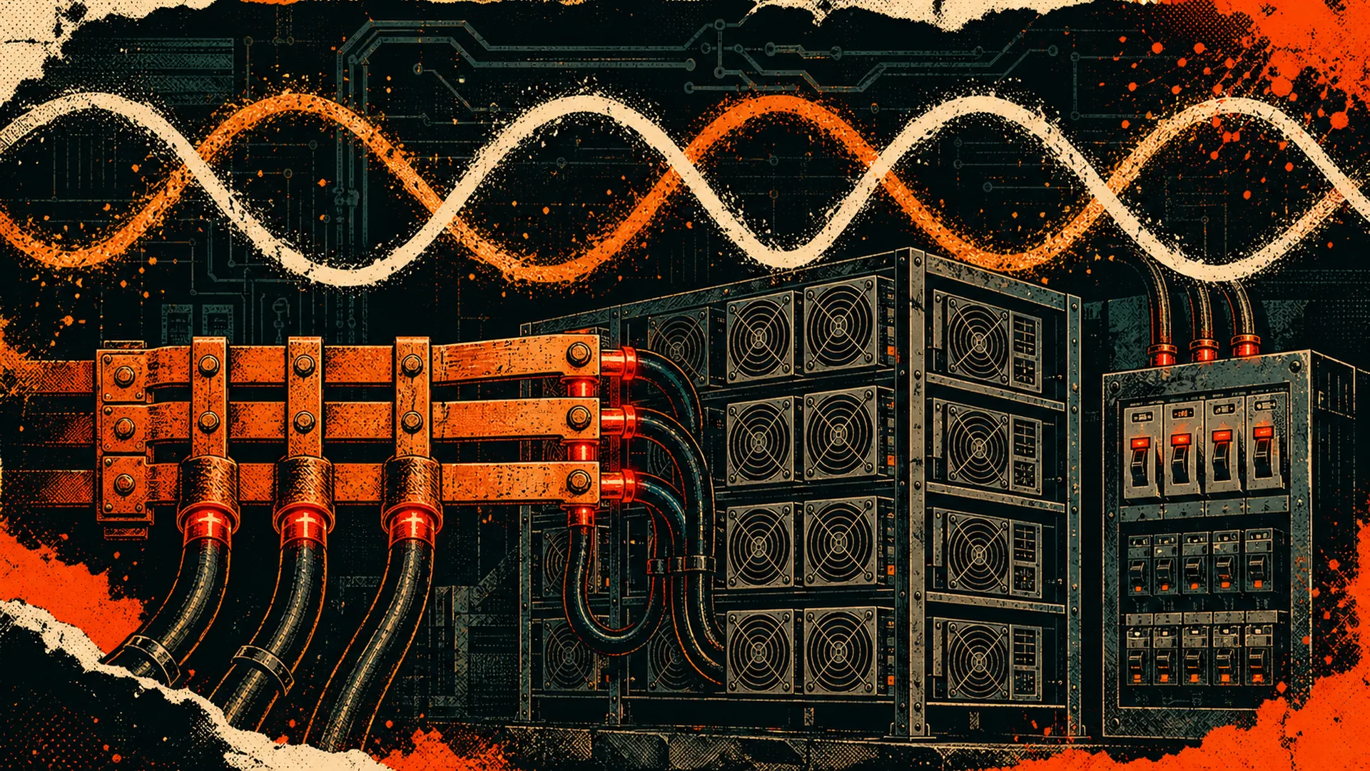
Here is the part that surprises operators coming from resistive-heater thinking. An ASIC PSU is a switching supply, and a switching supply is a non-linear load: instead of drawing a smooth sinusoidal current that tracks the voltage, it gulps current in short pulses near each voltage peak to refill its DC bus capacitors. That pulsed draw is mathematically equivalent to the fundamental 50/60 Hz current plus a stack of harmonic currents at integer multiples — the 3rd, 5th, 7th, 9th, and so on.

What the PSU does to the current waveform

Two numbers describe the damage. Total harmonic distortion (THD) is the harmonic content as a percentage of the fundamental; a clean sine is 0% and an uncorrected switching supply can exceed 100% THD on current. Crest factor is peak current divided by RMS current; a pure sinusoid has a crest factor of √2 (about 1.41), while an uncorrected non-linear load can hit 2–3, meaning brief current spikes far higher than the RMS reading suggests. High crest factor is why a breaker rated comfortably for the RMS draw can still trip, and why cheap PDUs and undersized neutrals run hot.

The good news: quality ASIC PSUs include active power factor correction (PFC), a switching stage that reshapes the input current back toward a sine wave. Active PFC pulls true power factor up to roughly 0.95–0.99 and pushes the bulk of the remaining distortion up to the switching frequency where it is easily filtered. It does not make the load perfectly linear, but it tames the low-order harmonics that do the most damage to your wiring. When you spec PSUs or evaluate refurbished units through ASIC repair, an intact active-PFC stage is one of the things worth verifying.

Triplen harmonics and the neutral

The 3rd harmonic and its odd multiples (the 9th and 15th — collectively the triplens) bite wye systems specifically. When balanced, the 60 Hz fundamental currents on the three phases cancel in the shared neutral, which is why a neutral can normally be sized like a phase conductor. Triplen harmonics do not cancel — they arrive in phase and add in the neutral, which under heavy non-linear load can carry up to roughly 200% of the phase current. A neutral sized for 100% will overheat, and because it is typically unprotected by an overcurrent device, that is a genuine fire hazard. In any hashcenter wye distribution with significant load, treat the neutral as a current-carrying conductor and oversize it.

Power factor, kVA, and utility penalties

Your utility meter cares about more than kilowatt-hours. It also cares about power factor — the ratio of real power (kW, the work done) to apparent power (kVA, the volts × amps the system must actually carry).

True power factor = displacement × distortion

Most people learn power factor as a phase-shift problem (current lagging voltage on motor loads), but that is only half the story for switching loads. True power factor is the product of two terms: the displacement factor (the classic phase shift between fundamental voltage and current) and the distortion factor (how far the current waveform departs from a sine). A switching supply with near-perfect displacement can still have a poor true power factor purely from harmonic distortion — which is exactly why active PFC exists: it attacks the distortion term that simple capacitor banks cannot fix.

How the utility bills it

Apparent power sizes the utility’s transformers and conductors, so many commercial tariffs either bill demand directly in kVA or apply a power-factor penalty when your PF drops below a threshold (commonly 0.90 or 0.95). At low PF you draw more current for the same real power — larger conductors, higher I²R losses in your own wiring, and a surcharge from the utility. A hashcenter of properly PFC-corrected PSUs running at 0.97–0.99 usually sails past these thresholds, but a fleet of cheap or failing supplies can quietly cost you on every invoice. When modeling operating cost, factor it in alongside the rate: our electricity-cost breakdown and mining calculators assume good power factor, an assumption worth verifying at the meter.

Power factor correction (PFC) at facility scale

Beyond the PSU’s built-in active PFC, larger sites sometimes add facility-level correction — harmonic or active filters tuned to the dominant orders. For a well-corrected ASIC fleet this is usually unnecessary, since the per-PSU active PFC already does the heavy lifting; it earns its keep mainly on legacy equipment, mixed loads, or strict utility metering. The honest answer is to measure first: put a power-quality analyzer on the service under full load, then decide whether external correction pays for itself.

Sizing the iron: the 80% continuous-duty rule

ASIC miners run 24/7. Under both the NEC and CEC, a load expected to draw maximum current for three hours or more is a continuous load, and continuous loads carry a sizing penalty. The NEC rule (210.20(A) for branch circuits, 215.3 for feeders) requires the overcurrent device and conductors to be rated for at least 125% of the continuous load. Flip that around and you get the familiar shorthand: a standard breaker may only be loaded to 80% of its rating continuously, because standard breakers are listed for 80% continuous operation. (There are 100%-rated assemblies, but they are special equipment, not your typical panel.)

So a 30A circuit is good for 24A of continuous ASIC load; a 50A circuit for 40A. Plan racks against the 80% number, not the breaker’s stamped rating. That single discipline prevents the most common scaling failure: breakers that hold for an hour and then trip once the room and the conductors reach steady-state temperature.

The 80% rule is the start, not the end. Conductor ampacity also derates for conditions of use:

Derating factor What triggers it Typical effect
Continuous load (125% / 80%) Any load running ≥3 hours (all ASICs) Load to 80% of breaker rating
Conductor bundling (NEC 310.15(C)(1)) More than 3 current-carrying conductors in a raceway 4–6 conductors → 80%; 7–9 → 70%; 10–20 → 50%
Ambient temperature correction Hot rooms above the 30°C table baseline Reduced ampacity; hashcenters run warm, so this matters
Neutral counted as CCC (310.15(E)) >50% of load is non-linear (i.e. your PSUs) Neutral counts toward the bundling tally and is oversized

These factors stack: a bundle of circuits in a warm room can lose a third or more of the conductor’s table ampacity once continuous, bundling, and temperature factors apply together. This is precisely where amateur hashcenters get into trouble — they size to the nameplate, ignore the conditions, and end up with warm conductors and tripping panels. Always have the final design stamped by a licensed electrician to your local code; the rules above are concepts, not a substitute for a permit.

Transformers and generators for non-linear loads

The harmonics that heat your neutral also heat your transformers and stress your generators. Both must be derated for non-linear load, because their nameplate ratings assume a clean sine wave.

Transformers. Harmonic currents cause extra eddy-current losses that scale with the square of frequency, so a transformer feeding switching supplies runs hotter than its kVA rating suggests. The fix is a K-rated transformer, designed with larger conductors, more cooling, and (per UL 1561) a neutral bus rated for at least 200% of full-load current to absorb the additive triplens. K-13 is the common specification for facilities dominated by non-linear electronic load; very heavy spectra call for K-20. As a rule of thumb, once non-linear load exceeds about 25% of a transformer’s capacity, specify a K-rated unit rather than derating a standard one.

Generators. If you back the site with a genset, oversize it. Manufacturers rate alternators assuming current THD below ~5%; feed them a non-linear fleet and the windings overheat while the automatic voltage regulator fights the distorted waveform. A common guideline is roughly 10% derate when non-linear load reaches ~30% of capacity, climbing to 15–25% oversizing where THD is high, with the practical target of keeping voltage THD on the generator bus under about 15%. A larger, lower-impedance generator also regulates voltage better and distorts less under load, so the oversizing buys stability as well as thermal margin.

PDU selection

The power distribution unit is where all of the above meets the rack. A few selection rules specific to ASIC hashcenters:

  • Match the service. Pick a PDU whose input plug and internal topology match your feed — single- or three-phase, at the right voltage (208V, 240V, 415V wye). Three-phase PDUs distribute outlets across the phases internally, solving half your balancing problem if you populate them evenly.
  • Match the cordset. Most air-cooled Antminer PSUs use a C13/C14 inlet; newer high-power and hydro units use a 16A C19/C20 cordset (a C20 plug into the PDU’s C19 outlet). Stock the right outlet, and never adapt around the rating.
  • Honor the 80% rule on the PDU too. A 30A PDU branch is a 24A continuous budget. Per-phase and per-branch metering lets you load each branch to spec and prove balance.
  • Rate for crest factor and harmonics. Choose PDUs and internal breakers rated for non-linear electronic load, not just resistive heaters — the pulsed draw is hard on undersized busbars.
  • Metered or switched? Metered units give per-outlet current for balancing and fault-finding; switched units add remote power-cycling, invaluable when a miner hangs off-site. For an operator running gear at home or in a small colocation cage, remote reboot often earns the premium.

Putting it together

The pattern for a serious hashcenter is consistent: a three-phase service with real headroom; a K-rated step-down transformer (and oversized generator, if backed up) feeding 208V or 415V-wye distribution; oversized neutrals; conductors and breakers planned to the 80% continuous rule with bundling and temperature derates applied; and PFC-corrected PSUs balanced across phases through metered PDUs. None of this replaces a licensed electrician and a permit — it gives you the vocabulary to design a site that scales without fighting its own wiring. For deeper hardware context the ASIC chip reference and operator field manual sit alongside this guide, and the sovereignty hub frames why running your own iron, on your own power, is worth the effort.

Frequently asked questions

Do ASIC miners need three-phase power?

No single miner needs three-phase — every ASIC power supply is a single-phase device, typically 200–240V. You move to three-phase service once you have many miners, because spreading the total load across three phases dramatically reduces the current any one conductor must carry, which means smaller wire, smaller breakers, and a service that a commercial building can actually provide.

What is the 80% rule and why does it apply to mining?

ASIC miners run continuously (maximum current for three or more hours), and the NEC and CEC require continuous loads to be sized at 125% — equivalently, a standard breaker may only be loaded to 80% of its rating. So a 30A circuit supports 24A of miner load, a 50A circuit 40A. Sizing to the stamped rating instead is the most common cause of breakers that trip only after the room warms up.

Why do switching power supplies cause harmonics?

A switching supply refills its DC bus in short current pulses near each voltage peak rather than as a smooth sine wave. That pulsed draw is equivalent to the fundamental frequency plus harmonic currents at the 3rd, 5th, 7th and higher orders, producing total harmonic distortion and an elevated crest factor that heat neutrals, transformers and generators beyond what an RMS reading suggests. Active power factor correction in quality PSUs reshapes the current and tames the worst of it.

Why must the neutral be oversized in a mining hashcenter?

In a balanced wye system the 60 Hz currents cancel in the neutral, but the triplen harmonics (3rd, 9th, 15th) produced by switching supplies do not cancel — they add. With heavy non-linear load the neutral can carry up to roughly 200% of the phase current, so a neutral sized for 100% will overheat. Because the neutral usually has no overcurrent protection, that is a fire risk, which is why K-rated transformers ship with a double-sized (200%) neutral.

Will a low power factor increase my electricity bill?

It can. Many commercial tariffs bill demand in kVA or apply a penalty when power factor falls below about 0.90–0.95. Low power factor means more current for the same real power, raising losses in your wiring and triggering utility surcharges. A fleet of PSUs with healthy active PFC usually runs 0.97–0.99 and avoids penalties; failing or low-quality supplies can quietly cost you. Measure power factor under full load before assuming you are clear.

Do I need a K-rated transformer and an oversized generator?

For any meaningful concentration of switching loads, yes — standard transformers and generators are rated for clean sine current and overheat on harmonic-rich load. Specify a K-rated transformer (K-13 for electronics-dominated facilities, K-20 for heavy spectra) once non-linear load passes ~25% of capacity, and oversize a backup generator by ~15–25% for high-THD load while keeping voltage THD under ~15%. Always confirm the final design with a licensed engineer for your jurisdiction.

ASIC Troubleshooting Database 650+ error codes with step-by-step fixes. Diagnose and repair your miner.
Try the Calculator

Bitcoin Mining Experts Since 2016

ASIC Repair Bitaxe Pioneer Open-Source Mining Space Heaters Home Mining

D-Central Technologies is a Canadian Bitcoin mining company making institutional-grade mining technology accessible to home miners. 2,500+ miners repaired, 350+ products shipped from Canada.

About D-Central →

Related Posts

Start Mining Smarter

Whether you are heating your home with sats, building a Bitaxe, or scaling up — D-Central has the hardware, repairs, and expertise you need.

Browse Products Talk to a Mining Expert